Friday 20 December 2013

FYP 2 Week 14 - FYP2 Presentation

As shown below is the project poster used to present during FYP 2 presentation. The schedule of this presentation was as mention in post in previous week. A day before presentation, we get to know our assessor name and our table number for the presentation.

At the day before also, me and my all friends who took FYP 2 was asking about the assessor that each of us get to know what type of person they are, will they be very strict, question a lot on our project, ask tricky question and many more.

On the presentation day, the hall was filled with the mood of Engineering Day as it was stated. Upon arriving at the hall, me myself and the entire student was busy putting up our project poster and setting up our project to get ready to be assessed by the assessor assigned to us.

My assessor was Miss Pusparini Dewi and Mr. Zaki who is both lecturers from Electrical section. I was first assessed by Miss Pusparini then followed by Mr. Zaki. The presentation I made to them went quite or can be said very well as they seem to be very satisfied with my explanation on the purpose and functionality of my project beside that I have answered the question they asked my, pretty well I guess.


Friday 13 December 2013

FYP 2 Week 13 – Preparation for FYP2 Presentation


As being schedule and noticed during the final FYP2 briefing session to all the diploma and degree student who taking FYP 2 module, the presentation Final Year Project 2 will be held on week 14 Friday 20 December 2013 from 8am to 4pm at the Gemilang Hall of UniKL BMI.

Several preparation made for FYP2 presentation are such as revise on theory of super capacitor used, final testing on project product, list down possible question that could be asked by assessor, think of point to be used in defending the project parts that does not yield the near expected results and most importantly my FYP poster which I had completed after getting advice and verifies the poster design made with my project supervisor, Mr. Shamsul Zahari.


Besides that, most importantly my body health was well taken cared to ensure that I will be in good condition to have self-confidence on myself in presenting my project excellently.

Friday 6 December 2013

FYP 2 Week 12 – Hardware Casing Development & Production

Product Packaging

                 To start with packaging, all the circuits are made sure to operate as required. First, each of the circuits and super capacitor bank are placed in box of it size as shown in figure a. Next, a bigger box that fit all the circuits box are made as in figure b. Lastly, the box is decorated with matching cover paper to make it more presentable as in figure c.


Figure showing packaging of circuit parts to form a product.


a


b


c

Friday 29 November 2013

FYP 2 Week 11 - Test & Troubleshoot Hardware Functionality

Testing


Figure showing completed circuit parts.


                 Testing of each circuit was then carried out to verify its functionality and work-ability by referring and comparing to the simulation results.

Friday 22 November 2013

FYP 2 Week 10 – Hardware Circuits Development

PCB Board Preparation


Figure showing steps involved in PCB board preparation.


Step 1


Step 2


Step 3


Step 4


Step 5

                 For printing of PCB design layouts to be done, first the plain PCB board of matching size to the design layouts need to be prepared following the steps shown in figure above.
                 Step 1 shows cutting of PCB design layouts from the printed OHP paper. In step 2, the plain PCB board are being cut following the size of cut out design from OHP sheet. Step 3 is about polishing the copper surface of plain PCB board to remove the oxide layer, followed by wiping of oxide dust with tissue paper and then with thinner as in step 4 and 5 respectively.


Ironing Method

Figure showing steps involved in printing PCB layout designed onto PCB board prepared.


Step 1


Step 2


Step 3


                 After preparing plain PCB board of matching size, printing of PCB design layouts on plain PCB can now be done following steps shown in figure above. First, the printed side of the OHP sheet need to be placed onto the copper surface of PCB board. Then, with the board and OHP sheet placed under a piece of white paper, the ironing can be done for printing process. Lastly, if the printing does not seem to be perfect with some of the dark line not appearing, then a permanent marker needs to be used to draw onto it.

Etching
                 Etching is a process of removing unwanted copper part on the PCB board designed, leaving only the copper part covered with permanent marker. To start etching process, the final product after the printing process as shown in step 1 of figure below need to be immersed in a container containing the etching acid which is dark brown in colour, as in step 2 below. The container need to be shaken gently and constantly for the acid to move around the surface of the copper layer of the board for more effective and rapid etching process. After etching the unwanted copper, now it can be clearly seen as in step 3 below that only the permanent marker lines are left over. In step 3, the board was cleaned with plain water to remove the acid layer.

Figure showing steps involved in etching process.


Step 1


Step 2


Step 3

Removing Marker Layer


                 Following after the etching process are process of removing permanent marker layer covering the copper layer. The permanent marker is removed using thinner by wiping with sponge as in figure a below. The result is PCB board with shiny copper design layout on top of it as in figure b below.
Figure showing process of removing permanent marker on PCB layout.


a


b

Checking Connectivity

                 When the multimeter touches connected copper lines, it gives reading of “0” as in figure b below. If the copper lines are disconnected, it gives reading of “1” as in figure a below.
Figure showing process of checking connectivity for the PCB layout.


a


b


Drilling

Figure showing PCB hand drill used in the project.

Figure showing drilling process.


Step 1


Step 2

                 Drilling of PCB need to be done carefully to ensure the PCB layouts are not damaged or disconnected. For that, the hand drill had to be held firmly and be pointed to the exact drilling point without shacking when started to drill as shown in step 1. The drilled hole need to be checked and cleaned from the board dust produced during drilling process as to prevent the drilled hole being blocked as shown in step 2 figure.

Completion To Hardware Development

Figure showing PCB circuits board prepared for the component placement and soldering.
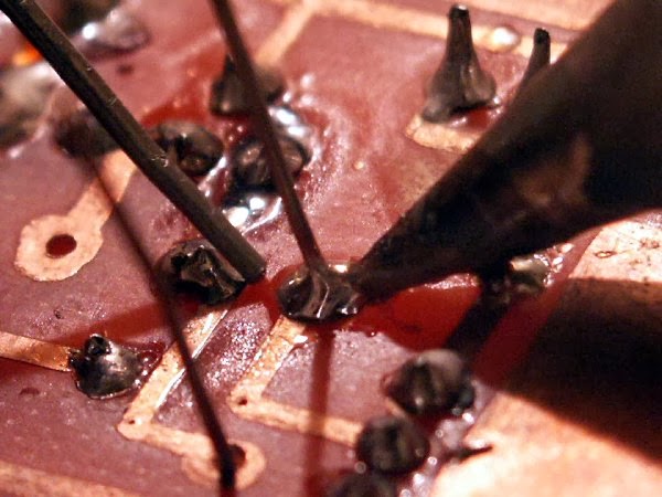
Soldering

Figure showing soldering process after the component placement.


a


b

                 To start soldering process, several tools and material have to be prepared first, such as soldering iron, solder lead, solder paste, sucker, and wet cloth as shown in figure a above. Before start soldering, the method need to be understand first in order to produce good soldering work. When soldering, first the copper pad surrounding the component leg need to be heated. Then, solder lead need to be touched on to the heated pad and let it melt to stick to the component leg perfectly as shown in figure b above.


Friday 15 November 2013

FYP 2 Week 9 –Test & Troubleshoot Circuits Functionality On Board

Figure showing testing of voltage comparator on breadboard.


                 Figure above shows charging process take place with RED LED turned on and GREEN LED turned on when the process completed respectively.

Figure showing testing of complete circuit on breadboard.


                 Figure above showing full view of charging process carried out on breadboard with RED LED turned on and voltmeter reading showing super capacitor charged up to 0.29V with the charging current of 0.09A (90mA).

Friday 8 November 2013

FYP 2 Week 8 – Construct Circuits On Board

            The component purchased was compared with the one used in the simulation as to make sure the correct component with correct value are bought.

            All the components were then grouped by their use and purpose for each particular circuit to be constructed. This made the circuit construction a lot easier as there will be no confusion in picking component while constructing the circuit on breadboard.

            The circuit construction was first begun with the voltage comparator, followed by AC-DC converters, then charging circuits and at last with voltage balancer circuits. Each single circuit constructed was tested individually for their functionality.

            At that time, since only one breadboard was available, so I tried to construct the circuits as compact as possible to fit all of it on that single breadboard available. The complete circuit on the breadboard was shown in figure below, from left is voltage comparator circuit, voltage balancer circuit, charging circuit, and rectifier circuit.


Figure showing complete circuit constructed on breadboard.